Fresnel Rhomb
Fresnel Rhomb and the effects of TIR phase shift
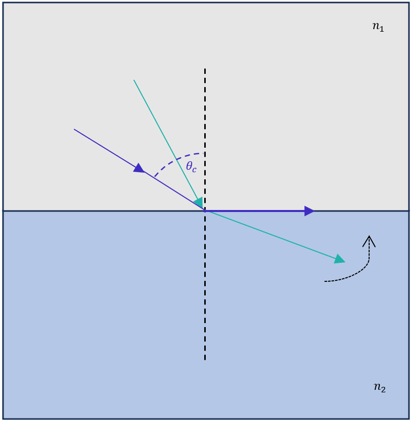
Total internal reflection occurs when the angle of incidence \( \theta_i \) exceeds the critical angle \( \theta_c \) , confining light within the higher-index medium \( (n_1 > n_2) \). In this regime, the Fresnel reflection coefficients for both polarizations become fully complex:
\[ r_{TE} = \frac{\cos\theta_i - j\sqrt{\sin^{2}\theta_i - n^{2}}} {\cos\theta_i + j\sqrt{\sin^{2}\theta_i - n^{2}}} \] \[ r_{TM} = \frac{-\,n^{2}\cos\theta_i + j\sqrt{\sin^{2}\theta_i - n^{2}}} {\,n^{2}\cos\theta_i + j\sqrt{\sin^{2}\theta_i - n^{2}}} \]Recall that what TM and TE actually mean is whether the electric field is perpendicular to the plane of incidence (TE), or the magnetic field is the one perpendicular to it (TM).

These complex Fresnel coefficients possess unit magnitude, so every bit of incident power is reflected—hence the qualifier total. What is less frequently emphasized is that they also impart a phase shift to the reflected electric field.
We therefore introduce the TE-polarized reflection coefficient
\[ r_{\text{TE}} = \frac{e^{-j\alpha}}{e^{j\alpha}} \]because
\[ E_r(z,t)=\frac{e^{-j\alpha}}{e^{j\alpha}}\, E_i\,e^{j(kz-\omega t)} =E_i\,e^{j\bigl(kz-\omega t-2\alpha\bigr)}, \]which reveals a phase shift of
\[ \phi_{\text{TE}} = -2\alpha. \]Expanding the TE-mode reflection coefficient with Euler’s identity gives
\[ \begin{aligned} r_{\text{TE}} &=\frac{\cos(-\alpha)+j\sin(-\alpha)} {\cos\alpha+j\sin\alpha} =\frac{\cos\alpha-j\sin\alpha} {\cos\alpha+j\sin\alpha}\\ &=\frac{\cos\theta_i -j\sqrt{\sin^{2}\theta_i-n^{2}}} {\cos\theta_i +j\sqrt{\sin^{2}\theta_i-n^{2}}} \end{aligned} \]We therefore have the geometric relations
\[ \cos\alpha=\cos\theta_i, \qquad \sin\alpha=\sqrt{\sin^{2}\theta_i-n^{2}}, \] \[ \tan\alpha= \frac{\sqrt{\sin^{2}\theta_i-n^{2}}}{\cos\theta_i}, \]and the associated phase shift becomes
\[ \phi_{\text{TE}} =-2\arctan\!\Bigl( \frac{\sqrt{\sin^{2}\theta_i-n^{2}}}{\cos\theta_i} \Bigr). \]Alternatively, for TM polarization we begin with
\[ r_{\text{TM}}=\frac{e^{-j(\alpha-\pi)}}{e^{j\alpha}}, \](an additional phase shift of \( \pi \) is included because the expression for \( r_{\text{TM}} \) already carries an overall minus sign).
\[ E_r =e^{-j(2\alpha-\pi)}\,E_i\,e^{j(kz-\omega t)}\hat{\mathbf z} =E_i\,e^{j\bigl(kz-\omega t-2\alpha+\pi\bigr)}, \] \[ \phi_{\text{TM}}=-2\alpha+\pi. \]Using Euler’s identity,
\[ \begin{aligned} r_{\text{TM}} &=\frac{e^{-j\alpha}\,e^{j\pi}}{e^{j\alpha}} =\frac{[\cos(-\alpha)+j\sin(-\alpha)] [\cos\pi+j\sin\pi]} {\cos\alpha+j\sin\alpha}\\ &=\frac{-\,\cos\alpha+j\sin\alpha} {\cos\alpha+j\sin\alpha}. \end{aligned} \]Recovering the familiar Fresnel form,
\[ r_{\text{TM}} =\frac{-\,n^{2}\cos\theta_i +j\sqrt{\sin^{2}\theta_i-n^{2}}} {\,n^{2}\cos\theta_i +j\sqrt{\sin^{2}\theta_i-n^{2}}}. \]Relating \( \alpha \) to the incidence angle \( \theta_i \) under total internal reflection,
\[ \cos\alpha=\cos\theta_i, \qquad \sin\alpha=\sqrt{\sin^{2}\theta_i-n^{2}}, \] \[ \tan\alpha =\frac{\sqrt{\sin^{2}\theta_i-n^{2}}}{n^{2}\cos\theta_i}, \]and the TM phase shift can be written compactly as
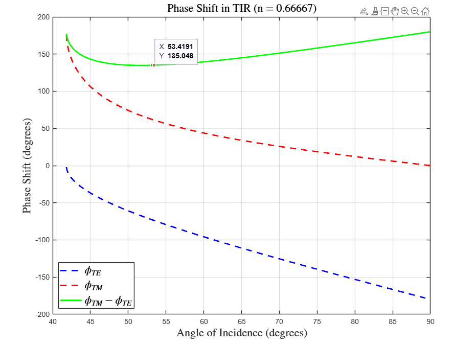
\[ \phi_{\text{TM}} =-2\arctan\!\Bigl( \frac{\sqrt{\sin^{2}\theta_i-n^{2}}}{n^{2}\cos\theta_i} \Bigr)+\pi. \]A plot of the phase difference can be seen below:

Keep in mind that the plot presented here pertains exclusively to an air–glass interface, with refractive indices \( n_2 = 1 \) (air) and \( n_1 = 1.55 \) (glass), leading to a ratio \( n = \dfrac{n_2}{n_1} \approx 0.666667 \).
We observe that at an incidence angle of roughly \( 53^{\circ}\!-\!54^{\circ} \), the phase difference between the TE and TM reflection coefficients approaches \( 135^{\circ} \). This behaviour can be exploited to engineer elements with different applications, such as the Fresnel rhomb.
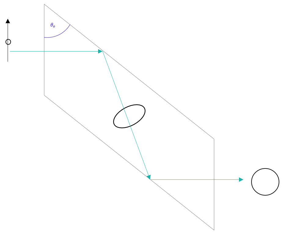
Fresnel’s rhomb is a glass prism that transforms linearly polarised light into nearly circularly polarised light by means of two carefully chosen total-internal reflections. A linearly polarised beam enters the first face at normal incidence, its electric-field vector oriented at \( 45^{\circ} \) to the long edge of the rhomb. Inside the prism, the beam undergoes two reflections, each at an incidence angle of about \( \theta_0 = 53^{\circ} \), thereby accumulating the requisite differential phase shift and resulting in a \( -\pi/2 \) phase shift.

Using the Jones matrix for a single internal reflection,
\[ \mathbf R =\begin{bmatrix} -r_p & 0 \\[4pt] 0 & r_s \end{bmatrix} =\begin{bmatrix} e^{j\phi_{\text{TM}}} & 0 \\[4pt] 0 & e^{j\phi_{\text{TE}}} \end{bmatrix} =e^{j\phi_{\text{TM}}} \begin{bmatrix} 1 & 0\\[4pt] 0 & e^{j\Delta} \end{bmatrix}, \qquad \Delta\equiv\phi_{\text{TE}}-\phi_{\text{TM}} =\frac{-3\pi}{4}. \]Remember we already accounted for the negative sign on the TM polarization. A Fresnel rhomb employs two such bounces, giving
\[ \mathbf R^{\,2} =e^{2j\phi_{\text{TM}}} \begin{bmatrix} 1 & 0\\[4pt] 0 & e^{-i3\pi/2} \end{bmatrix}, \]which introduces a net retardance of \( 3\pi/2 \) between the \( p \)- and \( s \)-polarized components. A linearly polarized input oriented at \( 45^{\circ} \) to the plane of incidence,
\[ \frac{1}{\sqrt{2}} \begin{bmatrix} 1\\[4pt] e^{j\pi/2} \end{bmatrix}, \]thus emerges as left-handed circular polarization (LCP).
How does changing the rhomb’s refractive index affect its performance? Whenever \( n \) departs from the nominal glass value (\( n \approx 1.55 \)), the incidence angle required to obtain the target \( 135^{\circ} \) phase retardation shifts accordingly. The accompanying script scans incidence angles for any chosen pair of indices and returns the one that satisfies \( \Delta\phi = 135^{\circ} \), providing a simple recipe for designing Fresnel rhombs made from alternative materials.
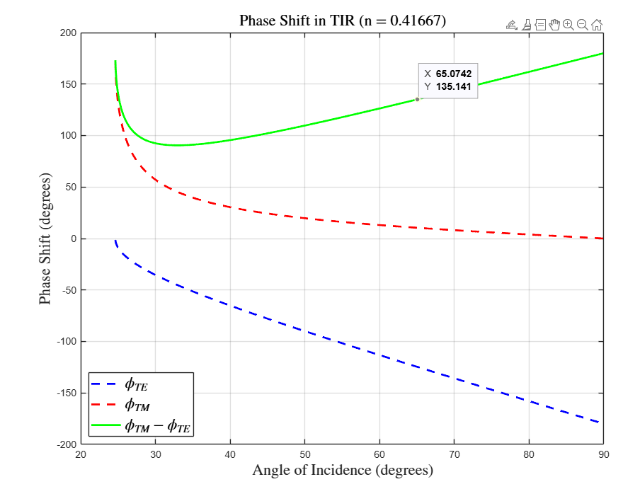
For instance, let us assume that the material of the rhomb is now diamond, with a refractive index of around \( n_1 = 2.4 \). The plot of the phase shift would be:

This leads to an angle of incidence of around \( 65^{\circ} \).
close all;
clc;
clear all;

% Phase shifts under Total Internal Reflection
% Define refractive index of transmitted medium (n < 1)
n = 1/2.4;  % Example value, you can change this

% Incident angles (in degrees)
theta_deg = linspace(asind(n) + 0.01, 89.9, 1000); % only angles above critical angle
theta_rad = deg2rad(theta_deg);  % Convert to radians

% Compute sine and cosine
sin_theta = sin(theta_rad);
cos_theta = cos(theta_rad);

% Argument under square root (evanescent part)
evan_TE = sqrt(sin_theta.^2 - n^2);
evan_TM = evan_TE;

% Phase shift expressions
phi_TE = -2 * atan(evan_TE ./ cos_theta);
phi_TM = -2 * atan(evan_TM ./ (n^2 * cos_theta)) + pi;

% Convert to degrees for plot (optional)
phi_TE_deg = rad2deg(phi_TE);
phi_TM_deg = rad2deg(phi_TM);

% Plot
figure;
plot(theta_deg, phi_TE_deg, '--b', 'LineWidth', 2); hold on;
plot(theta_deg, phi_TM_deg, '--r', 'LineWidth', 2); hold on;
plot(theta_deg, (phi_TM_deg - phi_TE_deg), 'g', 'LineWidth', 2);
xlabel('Angle of Incidence (degrees)','Interpreter','latex','FontSize',16);
ylabel('Phase Shift (degrees)','Interpreter','latex','FontSize',16);
title(['Phase Shift in TIR (n = ', num2str(n), ')'],'Interpreter','latex','FontSize',16);
legend('$\phi_{TE}$', '$\phi_{TM}$', '$\phi_{TM}-\phi_{TE}$','Location','SouthWest','Interpreter','latex','FontSize',16);
grid on;
Bibliography
Fowles, G.R. (1968). Introduction to Modern Optics (3nd Edition). Dover Publications Inc., New York, NY.
Hafner, J. (2024). Physics of Light and Materials [MOOC]. Coursera.